

Views: 0 Author: Site Editor Publish Time: 2026-09-23 Origin: Site


Industrial backup power systems carry zero margin for error. Facility managers and electrical engineers face dual operational risks when engineering these systems. Under-sizing leads to catastrophic facility downtime, severe voltage dips, and damaged manufacturing equipment during sudden grid failures. Conversely, over-sizing wastes capital and introduces severe mechanical degradation, specifically wet stacking, which destroys engine reliability over time.
Solving this engineering challenge requires translating complex facility electrical demands into precise equipment specifications. You must account for transient motor loads, harmonic distortion from non-linear loads, and the strict power quality requirements of sensitive electronics. Guesswork has no place on the job site. A systematic, evidence-based approach to generator kW calculation, comprehensive load profiling, and rigorous equipment evaluation is mandatory. This methodology guarantees mission-critical continuity, strict regulatory compliance, and maximum capital efficiency.
Accurate generator load calculation requires auditing steady-state running wattage, the transient starting wattage (surge loads) of inductive equipment, and the harmonic distortion from non-linear loads.
Over-sizing a generator by more than 30% of its rated capacity introduces severe mechanical risks, such as wet stacking, which drastically reduces engine lifespan and reliability.
Selecting the right industrial diesel generator depends on precise environmental derating (altitude, temperature), step load acceptance capabilities, and operational compliance (EPA tier ratings, NFPA 110).
Factoring in a strategic 10–20% capacity buffer prevents premature equipment obsolescence while accommodating future facility expansion, though load bank testing may be required in the interim.
Precision in diesel generator sizing dictates the survival of your facility during an outage. Under-sizing a unit triggers immediate, cascading failures across the electrical distribution system. When a generator lacks the transient capacity to handle a facility's load, you experience severe voltage sags. These dips cause the Automatic Transfer Switch (ATS) to sense a power anomaly and attempt to disconnect. They also trigger breaker trips and cause Programmable Logic Controllers (PLCs) on manufacturing lines to reboot. The alternator's magnetic field can collapse entirely under heavy transient loads, shutting down the backup system when the facility needs it most.
Over-sizing carries equally destructive mechanical consequences. Diesel engines require high combustion temperatures to operate efficiently. When a generator runs below 30% of its rated capacity, cylinder temperatures fail to reach the optimal threshold for complete combustion. Unburned fuel vapor condenses and mixes with soot. This forms a thick, dark liquid that leaks from the exhaust manifold—a condition known in the field as wet stacking. Over time, this carbonizes on the exhaust valves, turbocharger blades, and piston rings. The engine loses compression, burns oil, and eventually fails prematurely.
You must establish the exact scope of your backup requirements before calculating loads. Not every circuit requires emergency power. Categorize your facility's needs into distinct tiers based on operational priority. Life safety systems, such as emergency egress lighting, smoke evacuation fans, and fire pumps, form the absolute baseline. Critical operations, including data servers and active production lines, represent the next tier. Whole-facility backup is the most comprehensive approach but requires significantly larger equipment footprints.
Acceptable downtime windows dictate the required synchronization speed of the generator and the ATS. You must align your sizing strategy with baseline regulatory frameworks. The National Electrical Code (NEC) Article 700 covers Emergency Systems, mandating power restoration within 10 seconds for life safety loads. NEC Article 701 covers Legally Required Standby Systems, which have a 60-second restoration window. NEC Article 702 covers Optional Standby Systems, which have no strict time requirement but keep the business operational. Furthermore, NFPA 110 standards govern the performance, testing, and maintenance of these systems, classifying them by their required restoration time.
A rigorous facility audit forms the foundation of accurate generator load calculation. You must categorize every piece of equipment connected to the emergency panel. Resistive loads, such as incandescent lighting and industrial heating elements, draw steady power without surges. Their starting wattage equals their running wattage. Inductive loads, including heavy HVAC units, transformers, and industrial motors, require massive surges of power to start moving. Non-linear loads, such as UPS systems, variable frequency drives (VFDs), and LED drivers, chop the AC sine wave. This creates harmonic distortion that heats up the generator's alternator windings.
Identify your facility's peak demand using historical 15-minute interval utility data. This data reveals your actual maximum power draw, preventing reliance on theoretical maximums that inflate equipment size. Apply NEC Article 220 guidelines to calculate demand factors accurately. Before finalizing the alternator size, you must identify any phase imbalance in your existing 3-phase system. Heavy single-phase loads placed unevenly across a 3-phase panel will cause voltage irregularities, forcing the generator to work harder and potentially triggering protective shutdowns.
Motor starting creates the most significant engineering challenge in backup power design. When an induction motor starts, it draws Locked Rotor Amps (LRA). This temporary power draw can be six to eight times higher than the motor's Running Load Amps (RLA). You must calculate the multiplier effect for every large motor on the site. If multiple 100-horsepower motors start simultaneously upon power restoration, the combined LRA will stall the generator instantly.
Integrating soft starters and VFDs flattens this surge demand. These devices gradually ramp up the voltage supplied to the motor, significantly reducing the required starting wattage. This allows you to select a smaller, more efficient generator package.
Step Load Acceptance, or block loading, defines how much sudden load a generator can take without stalling or dropping voltage below acceptable limits. ISO 8528 defines performance classes (G1, G2, G3) for voltage and frequency recovery. Diesel engines are mechanical devices. When a massive electrical load hits the alternator, it creates magnetic resistance, dropping the engine RPM. The governor commands the fuel pump to inject more diesel, but the turbocharger needs time to spool up and push enough air into the cylinders to burn that extra fuel. You must sequence your loads through the ATS to guarantee the generator accepts power in manageable blocks.
Electrical data plates display requirements in volts and amps, but generators are rated in kilowatts (kW) and kilovolt-amperes (kVA). You must convert these figures accurately using standard electrical formulas.
| Phase Type | Formula for Apparent Power (kVA) | Formula for Real Power (kW) |
|---|---|---|
| Single-Phase | (Volts × Amps) / 1000 | kVA × Power Factor |
| Three-Phase | (Volts × Amps × 1.732) / 1000 | kVA × Power Factor |
Power Factor (PF) bridges the gap between real power (kW) and apparent power (kVA). In industrial applications, the standard Power Factor is typically 0.8. Real power represents the actual work performed by the electrical system. Apparent power includes the reactive power required to magnetize inductive motor cores. Always size the generator's engine based on the kW requirement and the alternator based on the kVA requirement.
Manual calculations provide a baseline, but modern industrial facilities require advanced modeling. Manufacturer-provided sizing software is indispensable for final specifications. These programs model complex scenarios that standard spreadsheets cannot handle. They simulate transient voltage dips during motor starts, calculate the harmonic distortion generated by specific UPS systems, and optimize complex load sequencing.
Using proprietary software verifies the selected unit meets all performance criteria under worst-case scenarios. It eliminates the risk of manual calculation errors when dealing with hundreds of mixed loads across a massive facility footprint.
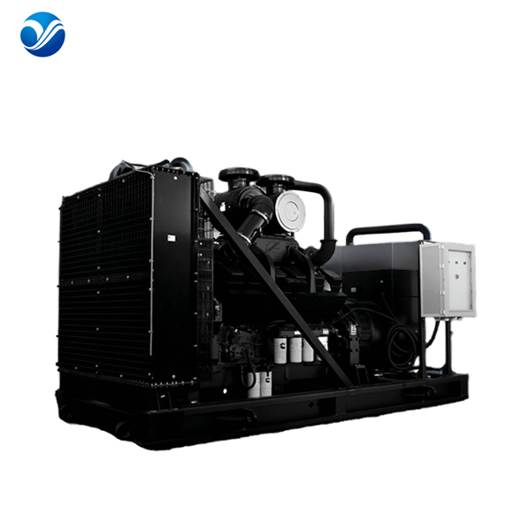
You must match the generator's ISO 8528 rating to your facility's operational profile. Applying the wrong rating voids warranties and guarantees equipment failure under load.
| Rating Type | Application Profile | Overload Capacity | Annual Run Time Limit |
|---|---|---|---|
| Standby Power | Emergency grid outages, varying loads | None (0%) | Typically under 200 hours |
| Prime Power | Remote off-grid operations, peak shaving | 10% for 1 hour every 12 hours | Unlimited hours |
| Continuous Power | Utility-scale baseload, constant loads | None (0%) | Unlimited hours |
Selecting an industrial diesel generator with a Standby rating for a Prime power application will cause rapid engine degradation due to sustained thermal stress. The engine block and cooling system are simply not engineered for continuous, heavy-duty cycles.
A highly effective engineering strategy involves decoupling the alternator size from the engine size. Non-linear loads, such as large UPS systems and VFDs, create severe harmonic distortion. This distortion causes the alternator windings to overheat. To combat this, engineers up-size the alternator end (e.g., specifying a 1000 kVA alternator on an 800 kW engine) to lower the subtransient reactance and handle the thermal stress.
Simultaneously, you must keep the diesel engine properly sized to the actual kW load. If you up-size the entire generator package just to get a larger alternator, the engine will run under-loaded. This leads directly to low exhaust temperatures and wet stacking. Up-sizing the alternator while maintaining a strictly matched engine displacement guarantees both electrical stability and mechanical longevity.
Nameplate ratings reflect performance under standard laboratory conditions. Real-world site conditions drastically alter actual power output. You must apply environmental derating factors before finalizing your specifications.
Altitude derating is governed by physics. As elevation increases, air density decreases. Thinner air reduces the amount of oxygen available for combustion in the engine cylinders. A diesel engine loses roughly 3% of its power for every 1,000 feet of elevation above 3,300 feet. If your facility is in a high-altitude region, a 1000 kW generator will not produce 1000 kW.
Ambient temperature also impacts performance. High temperatures reduce the cooling system's efficiency and lower the density of the intake air. Alternator performance degrades in extreme heat due to increased winding resistance. You must derate the equipment by approximately 1% for every 10 degrees Fahrenheit above 104°F (40°C). Failure to account for site-specific derating guarantees the generator will stall during a summer grid failure.
The physical iron is only half the equation. You must evaluate tier-one manufacturers based on their control ecosystems and aftermarket support. Proprietary control systems dictate how well the generator integrates with your facility. For example, evaluating a Cummins diesel generator requires looking at its integrated PowerCommand controls, which offer advanced diagnostic reporting and simplified paralleling capabilities.
Assess parts availability and the proximity of certified local technicians. A premium generator holds no value if a replacement sensor takes three weeks to ship to the job site. Evaluate warranty terms strictly. Verify the manufacturer has a proven track record of supporting legacy equipment, as industrial generators are expected to operate reliably for 20 to 30 years.
Procurement decisions require balancing upfront costs against long-term operational realities. A cheaper generator often carries higher fuel consumption rates and shorter maintenance intervals. You must analyze the trade-off between the initial CapEx of the equipment and the OpEx required to keep it running over a 25-year lifecycle.
Advanced emissions control systems heavily influence this balance. EPA Tier 4 Final compliance requires complex exhaust aftertreatment, including Selective Catalytic Reduction (SCR) and Diesel Particulate Filters (DPF). While these systems guarantee environmental compliance, they increase upfront costs and introduce strict maintenance realities. DPFs require periodic active regeneration to burn off accumulated soot, and SCR systems require continuous Diesel Exhaust Fluid (DEF) replenishment. If the generator runs lightly loaded, the DPF clogs rapidly, forcing the system into a derated limp mode.
Do not underestimate the hidden timelines associated with local compliance. Air Quality Management District (AQMD) permitting can delay a project by months. You must submit detailed emissions data and operational profiles to secure permits before breaking ground.
Noise ordinances dictate the required acoustic enclosures. Hospitals and residential-adjacent facilities often require hospital-grade silencers and custom sound-attenuated enclosures to meet strict decibel limits at the property line. Exhaust emission limitations may restrict the number of hours you can run the generator for testing and maintenance. Factor these regulatory hurdles into your project timeline and budget from day one.
Facilities evolve. Buying a generator strictly for today's load guarantees premature obsolescence. Building in a 10–20% capacity buffer accommodates planned facility expansions, new production lines, or HVAC upgrades. However, this buffer introduces the risk of light-loading the engine in the short term.
To mitigate this, compare the trade-offs of paralleling multiple smaller generators versus installing one massive unit. Paralleling three 500 kW units instead of one 1500 kW unit offers N+1 redundancy. If one unit fails, the other two continue supporting critical loads. Paralleling also allows the system to run only the engines needed to meet the current demand, ensuring better low-load fuel efficiency and preventing wet stacking. The trade-off is a larger physical footprint and more complex, expensive paralleling switchgear.
Diesel fuel is the lifeblood of the system, but it is inherently unstable. You must size your fuel storage based on regulatory requirements and operational logic. Hospitals and data centers typically require 48 to 72 hours of runtime at full load. You must decide between a large sub-base belly tank that sits directly under the generator or external day tanks fed by a remote bulk storage facility.
Diesel fuel degrades within six to twelve months. Condensation inside the tank promotes microbial growth, which clogs fuel filters and destroys fuel injectors. Mitigation requires the mandatory integration of automated fuel polishing systems. These systems periodically cycle the fuel through heavy-duty centrifuges and multi-stage water separators. Additionally, you must implement a strict schedule for biocide treatments and chemical stabilizers to maintain fuel integrity.
Successful backup generator sizing means nothing if the physical installation fails. Automatic Transfer Switch (ATS) compatibility is paramount. The ATS must be rated for the full generator output, the total facility load, and the available fault current withstand ratings. An under-rated ATS will weld its contacts shut during a short circuit event.
Structural and civil engineering prerequisites require rigorous attention. The concrete pad must bear the immense operational weight of the unit while preventing differential settlement. You must install proper spring-type vibration isolation mounts to prevent engine harmonics from damaging the facility structure. Exhaust routing must comply with fire codes, utilizing proper thimbles for roof penetrations and ensuring toxic gases dissipate safely away from building air intakes.
Commissioning is the final, critical step. You cannot rely on the facility's day-one load to test the system. Initial and routine load bank testing is an absolute necessity. A resistive load bank turns electrical energy into heat, applying an artificial, full-capacity electrical load to the generator. This proves the system can handle its nameplate rating, verifies ATS sequencing, and burns off any carbon deposits accumulated during low-load testing.
Proper backup generator sizing is a strict engineering exercise where precision dictates facility reliability, safety, and capital efficiency. Relying on estimates or rule-of-thumb calculations exposes your operation to catastrophic downtime or severe mechanical degradation. You must audit your loads, account for transient surges, and apply exact environmental derating factors.
When evaluating options, prioritize manufacturers with robust local support networks, exact power ratings matching your specific load profile, and proven compliance records. The physical equipment is only as reliable as the engineering and maintenance ecosystem supporting it.
Take the following actionable steps to secure your facility's power infrastructure:
Engage a certified electrical engineer to conduct a formal, comprehensive load study of your entire facility.
Gather the last 12 months of 15-minute interval utility data to establish your true peak demand baseline.
Identify all non-linear loads and large inductive motors to calculate precise harmonic distortion and Locked Rotor Amp requirements.
Request site-specific, altitude- and temperature-derated quotes from tier-one vendors.
Implement a mandatory load bank testing and automated fuel polishing protocol into your facility maintenance schedule.
A: There is no safe rule of thumb for industrial applications. Relying on square footage or generic multipliers leads to dangerous sizing errors. You must calculate the exact running wattage, account for the transient starting surge of inductive motors, factor in harmonic distortion from non-linear loads, and apply a 10-20% buffer for future expansion.
A: For a three-phase system, multiply the Volts by the Amps, then multiply by 1.732. Divide that total by 1000 to get the apparent power in kVA. To find the real power in kW, multiply the kVA by the system's Power Factor, which is typically 0.8 for industrial environments.
A: Oversizing causes the engine to run below its optimal operating temperature. This prevents complete fuel combustion, leading to wet stacking. Unburned fuel and soot accumulate in the exhaust system, degrading engine performance, causing carbon buildup on valves, and drastically shortening the equipment's lifespan.
A: Inductive motors require massive power surges to start. The Locked Rotor Amps (LRA) can be 6 to 8 times higher than the motor's steady Running Load Amps (RLA). The generator's alternator must be sized to handle this temporary kVA spike without allowing voltage to dip below acceptable thresholds.
A: Kilowatts (kW) represent real power, which is the actual work performed by the electrical system. Kilovolt-amperes (kVA) represent apparent power, which includes both the real power and the reactive power needed to magnetize inductive equipment like motors. Generators are sized with engine capacity in kW and alternator capacity in kVA.
A: Step load acceptance defines how much sudden electrical load a generator can take in a single block without stalling the engine or causing severe voltage drops. Because turbocharged diesel engines need time to spool up, they cannot always accept 100% of their rated load instantly. Loads must often be sequenced through the transfer switch.


