

Views: 0 Author: Site Editor Publish Time: 2026-07-02 Origin: Site


Reliable facility uptime depends on a precise understanding of the mechanical and electrical realities governing backup power systems. Procuring an industrial generator based solely on top-line wattage often leads to critical failures, such as under-sizing for motor starting loads, incompatible fuel logistics, or unacceptable harmonic distortion damaging sensitive equipment. To make an informed procurement decision, technical buyers must understand exactly how a power generator converts mechanical energy into electrical current, how individual components dictate performance, and which mechanical trade-offs impact long-term reliability.
Power generators do not "create" electricity; they act as an "electron pump" using electromagnetic induction to force the movement of electrical charges already present in their windings through an external circuit.
The system relies on a multi-stage energy conversion chain: chemical energy (fuel) to thermal energy (combustion) to mechanical energy (rotational force) to electrical energy.
The performance of an industrial generator relies heavily on the synergy between the prime mover (engine) and the alternator (rotor/stator), which dictates load acceptance and power quality.
Selecting the right system requires evaluating transient response capabilities, fuel storage realities, and specific operational designations (Standby, Prime, or Continuous).
Automatic Voltage Regulation (AVR), robust lubrication/cooling systems, and advanced digital control panels are critical evaluation dimensions for facilities running sensitive electronics or operating in extreme environments.
A generator functions through a strict multi-stage energy conversion chain. It begins with chemical energy stored in fuel. Through the combustion process within the engine cylinders, this chemical energy transforms into thermal energy. The rapid expansion of gases during combustion forces the engine pistons downward, converting thermal energy into mechanical rotational energy at the crankshaft. This shaft torque transfers directly to the alternator, which executes the final conversion from mechanical rotational energy into electrical energy.
The final stage relies entirely on Faraday’s Law of electromagnetic induction. In practical terms, a generator moves a magnetic field across electrical conductors to induce a voltage. The engine provides the mechanical energy required to spin a rotor inside a stationary stator. The spinning rotor creates a rotating magnetic field. As this magnetic field sweeps past the copper wire windings of the stator, it forces the existing electrons within those wires to flow. This movement of electrons constitutes the electrical current that powers an external circuit.
Understanding the mechanics of current flow requires differentiating between Alternating Current (AC) and Direct Current (DC) generation. In AC alternators, the magnetic field rotates while the armature windings remain stationary, often utilizing slip rings and brushes to transfer excitation current to the rotor. DC generators reverse this arrangement, using commutators to convert the alternating current generated in the rotating armature into a direct current output. AC remains the standard for industrial applications because it allows for efficient voltage stepping via transformers, minimizing power loss during long-distance transmission across a facility.
Maintaining the magnetic field requires a robust excitation system. Self-excited systems draw power directly from the alternator's main output to feed the rotor, which can cause voltage dips during heavy motor starting. Auxiliary winding systems provide a separate power source within the stator to sustain the magnetic field under load. Permanent Magnet Generators (PMG) offer the highest level of stability by utilizing an independent permanent magnet to supply excitation current, ensuring the magnetic field remains strong even when massive inrush currents attempt to drag down the system voltage.
| Excitation System | Mechanism | Motor Starting Capability | Best Application |
|---|---|---|---|
| Self-Excited (Shunt) | Draws power from main stator output | Low to Moderate | Basic standby power, resistive loads |
| Auxiliary Winding (AREP) | Uses separate windings in the stator | High | Commercial facilities, mixed loads |
| Permanent Magnet (PMG) | Independent magnet provides excitation | Excellent (up to 300% short circuit current) | Data centers, heavy industrial motors |
The engine acts as the prime mover, determining the total mechanical power and torque available to the alternator. Engine displacement, cylinder configuration, and aspiration dictate how much rotational force the system can sustain under heavy electrical loads. Fuel selection directly impacts response time and energy density. Diesel provides high energy density and rapid load acceptance, making it ideal for emergency standby applications. Natural gas offers continuous fuel supply without on-site storage requirements but may face supply chain vulnerabilities during widespread seismic events. Bi-fuel and propane systems offer alternative logistical advantages depending on site-specific storage capabilities and emissions constraints.
The alternator executes the mechanical interaction between the moving rotor (inductor) and the stationary stator (armature). The physical design of the stator windings dictates the quality of the electrical output. Engineers often specify a 2/3 winding pitch design to eliminate the 3rd harmonic, drastically reducing total harmonic distortion (THD) and preventing excessive neutral currents. Insulation class also plays a vital role. Class H insulation withstands higher operating temperatures than Class F, allowing the alternator to handle intense heat buildup during prolonged operation without degrading the copper windings.
The Automatic Voltage Regulator (AVR) serves as the gatekeeper of power quality. It continuously monitors the output voltage from the stator. When a heavy load connects to the generator, the voltage naturally drops. The AVR detects this drop and instantly increases the DC excitation current sent to the rotor. This strengthens the magnetic field, pulling the output voltage back to the target level. Precise AVR response is a non-negotiable success criterion for data centers, telecommunications hubs, and healthcare facilities, where even minor voltage fluctuations can damage sensitive microprocessors or disrupt critical life-safety equipment.
Thermal management is a constant mechanical challenge. Combustion processes and electrical resistance generate massive amounts of heat that must be dissipated to prevent catastrophic failure. Liquid-cooled systems utilize a mixture of water and glycol pumped through engine block jackets, transferring heat to a large radiator cooled by an engine-driven fan. Direct air-cooled systems force ambient air across finned engine components, typically reserved for smaller units. Exhaust systems must route toxic combustion gases safely away from the facility while utilizing industrial silencers to meet local noise ordinances, heavily influencing indoor versus outdoor installation requirements.
The starting system relies on heavy-duty lead-acid or AGM batteries to power high-torque starter motors. These motors must crank the engine rapidly to initiate combustion, enabling the rapid-start sequences essential for emergency standby systems to assume the facility load within ten seconds. The lubrication system utilizes a pressurized oil pump, heavy-duty oil filters, and dedicated coolers to maintain a hydrodynamic film between moving metal parts, preventing mechanical friction and engine seizure during prolonged operations. The fuel delivery system utilizes integrated day tanks, mechanical fuel pumps, and multi-stage fuel filtration, including water separators, to ensure only clean, water-free fuel reaches the high-pressure fuel injectors.
The digital control panel functions as the central nervous system of the generator. It aggregates sensor data to display vital monitoring parameters, including electrical frequency (Hz), voltage (V), current (A), engine oil pressure, coolant temperature, and total run hours. Beyond monitoring, the control panel executes critical safety shutdown triggers. If sensors detect engine overspeed, critically low oil pressure, or high coolant temperatures, the control panel immediately cuts fuel delivery and shuts down the unit to prevent catastrophic mechanical destruction.
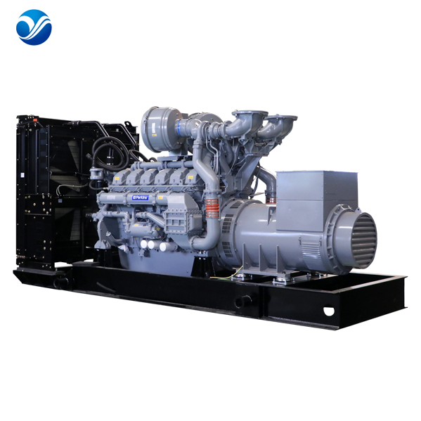
Generators carry specific operational ratings based on ISO 8528 classifications. Standby generators are designed strictly for emergency use during utility outages. They carry strict limitations on annual run hours (typically capped around 200 to 500 hours) and average load factors. Prime power generators are built for extended run times in remote locations where utility power is entirely unavailable. They feature robust cooling and engine components designed to handle variable load management and high load factor tolerances indefinitely. Continuous power generators are engineered for constant, unvarying loads, such as base-load power for a remote mining operation. They require heavy-duty component specifications to prevent premature thermal and mechanical degradation under relentless 100% load demands.
| ISO 8528 Rating | Typical Run Hours/Year | Average Load Factor | Overload Capability |
|---|---|---|---|
| Emergency Standby (ESP) | 200 - 500 hours | 70% of rated capacity | None |
| Prime Power (PRP) | Unlimited | 70% - 80% of rated capacity | 10% overload for 1 hour in 12 |
| Continuous Power (COP) | Unlimited | 100% of rated capacity | None |
Conventional generators run at a constant, fixed engine speed (typically 1800 RPM or 3600 RPM) to maintain a steady 60Hz or 50Hz electrical frequency. If the engine speed drops, the frequency drops, which can damage connected equipment. Inverter generators decouple engine speed from electrical frequency. They produce raw, high-frequency AC power, convert it to DC power via a rectifier, and then use microprocessors to invert it back to exceptionally clean AC power. This allows the engine to throttle down during light loads, saving fuel and reducing noise. The premium cost of inverter technology is justified when a facility requires ultra-stable, clean power for sensitive electronics, whereas heavy industrial motor loads generally demand the raw, high-surge capacity of conventional power.
Accurate load calculation dictates system viability. Facilities must differentiate between steady-state running wattage and the high inrush current required by heavy industrial motors, pumps, and HVAC compressors. A motor may require three to six times its running wattage for a few seconds during startup. This surge requirement dictates the alternator sizing. Under-sizing the generator leads to severe voltage dips, frequency collapse, and failure to start critical equipment. Conversely, over-sizing a diesel generator leads to wet stacking, a condition where unburned fuel and carbon accumulate in the exhaust system due to low combustion temperatures caused by insufficient engine loading.
Transient response defines the generator's speed of recovery for voltage and frequency when a large block load is suddenly applied or removed. When a massive chiller plant kicks on, the generator experiences a violent mechanical drag. Engine displacement, governor precision, and turbocharging configurations heavily influence recovery time. Single-stage turbochargers may experience "turbo lag," delaying the air required for rapid combustion, while advanced dual-stage turbochargers provide immediate air density. These mechanical realities determine an industrial generator's ability to meet strict ISO 8528 G2 or G3 standards for load acceptance and power stability.
Industrial power systems must navigate a strict regulatory landscape regarding exhaust emissions. The EPA enforces Tier 2, Tier 3, and Tier 4 Final emission standards depending on the generator's size and application (standby versus non-emergency). Achieving Tier 4 Final compliance requires significant mechanical additions to the exhaust stream. Manufacturers integrate Diesel Particulate Filters (DPF) to capture soot, and Selective Catalytic Reduction (SCR) systems utilizing Diesel Exhaust Fluid (DEF) to neutralize nitrogen oxides. These aftertreatment systems drastically increase the physical footprint of the installation and introduce new maintenance overhead, requiring regular DEF replenishment and DPF regeneration cycles.
Backup power systems face hidden risks during extended periods of inactivity. Diesel fuel degrades over time, suffering from microbial growth, oxidation, and water accumulation due to tank condensation. Degraded fuel clogs filters and destroys high-pressure fuel injectors instantly upon startup. Mitigating this risk requires a rigorous preventative maintenance schedule. Facilities must implement regular load bank testing to burn off carbon deposits, conduct routine fluid analysis, replace starting batteries on a strict chronological schedule, and utilize automated fuel polishing systems to cycle and filter stored diesel, ensuring the mechanical components function instantly when a utility outage occurs.
Understanding the mechanical conversion of fuel to electricity via electromagnetic induction forms the foundation of sound generator procurement. Evaluating the specific interactions between the engine, alternator, and control systems allows facility managers to bypass superficial wattage metrics and focus on actual performance capabilities. Base initial selections on fuel availability and the facility load profile, distinguishing clearly between standby and continuous operational needs. Follow this with a strict evaluation of alternator winding pitch, excitation type, and transient response capabilities to ensure power quality matches equipment tolerances.
Conduct a comprehensive facility load study to quantify exact running watts and peak motor starting requirements.
Consult with a power systems engineer to specify the optimal excitation system and alternator insulation class for your specific environment.
Establish a strict preventative maintenance protocol that includes automated fuel polishing and annual load bank testing.
Verify local emissions regulations to determine if Tier 4 Final aftertreatment systems are legally required for your intended run hours.
A: An ATS continuously monitors utility power. When it detects a voltage drop or complete outage, it signals the generator to start. Once the generator reaches stable voltage and frequency, the ATS mechanically disconnects the facility from the utility grid and connects it to the generator power feed.
A: A well-maintained industrial diesel generator typically lasts between 15,000 and 30,000 operating hours. For a standby unit running only during outages and monthly testing, this can equate to a chronological lifespan of 20 to 30 years before requiring a major engine overhaul.
A: Sizing requires calculating the total steady-state running wattage of all critical equipment and adding the highest peak starting surge wattage of the largest motors. Engineers use load sizing software to account for voltage dip tolerances and harmonic distortion limits.
A: Surging or hunting usually stems from fuel delivery issues, such as clogged fuel filters, air trapped in the fuel lines, or degraded diesel. It can also be caused by a failing mechanical governor or a miscalibrated electronic engine control module struggling to match engine speed to load fluctuations.
A: While the main alternator produces AC power for the facility load, most generators also incorporate a small secondary DC alternator driven by the engine belt. This DC system charges the starting batteries and powers the digital control panel.
A: A self-excited alternator draws its excitation power directly from its own main output terminals, meaning a heavy load can temporarily collapse the magnetic field. A Permanent Magnet Generator (PMG) uses a separate, dedicated magnet to supply excitation power, ensuring a stable magnetic field regardless of output voltage drops.
A: Wet stacking occurs when a diesel engine runs at light loads, preventing exhaust temperatures from reaching the level required to burn all injected fuel. Unburned fuel and soot accumulate in the exhaust. It is prevented by running the generator at a minimum of 30% to 50% of its rated load during testing.


