

Views: 0 Author: Site Editor Publish Time: 2026-08-14 Origin: Site


When utility power fails, facility survival depends entirely on a generator’s ability to instantly accept and stabilize the electrical demand. Unverified generators often suffer from voltage collapse, frequency drops, or engine stalling when subjected to sudden, heavy electrical loads. These block loads lead to catastrophic downtime for mission-critical operations. A generator that starts and idles perfectly under no-load conditions provides false security. True operational readiness can only be proven under simulated real-world stress. To mitigate deployment risks, a rigorous diesel generator manufacturer executes comprehensive Factory Acceptance Testing (FAT). We utilize load banks and transient response analysis to prove the equipment meets exact performance specifications before it leaves the facility. Skipping this step guarantees failure when you need emergency power the most.
Block Load vs. Step Load: True load acceptance verification requires testing both 100% single-step block loads and incremental step loads to measure transient voltage and frequency response.
Standardized Compliance: Reputable manufacturers validate performance against strict regulatory frameworks, primarily ISO 8528-5 (transient response classes) and NFPA 110 (emergency standby power systems).
Form Factor Variables: Enclosure types—from open skids to sound-attenuated containers—impact thermal dynamics and airflow, requiring specific load testing parameters for each configuration.
Evidence-Based Procurement: Buyers must demand comprehensive FAT reports detailing resistive/reactive load bank results, baseline gauge metrics, exhaust gas temperatures, and recovery times to ensure operational readiness.
Load acceptance defines how a power system manages sudden electrical demand. We measure this through transient response. When a facility transfers its load to emergency power, the alternator experiences an immediate magnetic drag. This drag causes a sudden voltage dip. Simultaneously, the mechanical resistance on the engine spikes, causing a frequency droop. The system must detect these drops instantly. The engine governor injects more fuel to regain speed. The automatic voltage regulator (AVR) increases excitation current to restore voltage. Recovery time measures how fast the system stabilizes these metrics within acceptable parameters. In the field, a delay of just a few hundred milliseconds can trip sensitive breakers.
Many operators rely on simple dry runs to verify equipment. Starting an engine and letting it idle proves very little. A no-load run only confirms the starter motor and basic fuel delivery function. Mechanical and electrical faults rarely manifest during idle operation. Alternator winding insulation weaknesses only show under high current. Fuel injector spray patterns only optimize under high pressure. Cooling system restrictions only cause overheating when the engine rejects maximum heat. Dynamic load testing forces the system to operate at its rated current. This exposes hidden defects before the unit reaches the installation site. We never trust an engine that hasn't sweat under a full load bank.
A successful load test goes far beyond keeping the engine running. The primary goal is maintaining power quality. Sensitive downstream equipment requires tight voltage and frequency tolerances. Uninterruptible Power Supply (UPS) systems will reject generator power if the frequency fluctuates excessively. Medical imaging devices will shut down if voltage dips below specific thresholds. Buyers must evaluate the transient response data. The success criteria involve measuring the maximum deviation percentage and the exact recovery time in milliseconds. If the power quality falls outside the acceptable window, the test is a failure. You must demand the raw oscilloscope data to verify these claims.
The engine governor and the AVR act as the central nervous system during load acceptance. The governor monitors engine RPM, which directly dictates electrical frequency. When a block load hits, the RPM drops. The governor must react in milliseconds to open the fuel rack. If it reacts too slowly, the engine stalls. If it overcompensates, the frequency overshoots, potentially damaging facility equipment. The AVR monitors the output voltage. Sudden loads cause the alternator's magnetic field to sag. The AVR must instantly push more direct current into the exciter field. Manufacturer verification focuses heavily on calibrating the interaction between these two components. Tuning them requires extensive trial and error on the test bench.
Before applying any artificial load, technicians execute a mandatory pre-load checklist. This ensures the unit is safe to test and establishes baseline metrics. We never skip these steps on the test stand.
Verify engine oil pressure at idle and rated speed using calibrated mechanical gauges.
Confirm coolant temperature is rising normally without localized boiling in the water jacket.
Check battery voltage and charging alternator output under initial startup conditions.
Inspect fuel delivery systems for leaks, pressure drops, or air intrusion in the lines.
Ensure all safety shutdown sensors are active and responsive by simulating fault conditions.
Torque all alternator output lugs to specification to prevent arcing during high-current draws.
Technicians must also calibrate control panels and analog gauges. Accurate data logging relies entirely on precise sensor inputs. Applying loads to an uncalibrated system renders the FAT report useless. We use independent thermal imaging cameras to verify the onboard temperature sensors.
Comprehensive testing requires specialized load bank equipment. Resistive load testing simulates standard heating and lighting loads. This operates at a 1.0 power factor, drawing pure active power (kW). Reactive load testing simulates motor and transformer loads. This operates at a lower power factor, typically 0.8, drawing inductive loads (kVAR). Combining both methods provides a true kVA simulation. This reflects real-world facility demands accurately. Testing only kW ignores the magnetic stress placed on the alternator by facility motors and HVAC compressors. We always deploy combined resistive/reactive load banks for units over 500kW.
Test duration establishes thermal equilibrium. A quality manufacturer runs the generator at full rated load for extended periods. This typically lasts between one and four hours depending on the specification. The goal is to maximize thermal stress. The cooling package must stabilize coolant and oil temperatures. The alternator windings must reach their maximum operating temperature without degrading the insulation. Short tests fail to prove continuous operational viability. If the radiator is undersized, it will boil over at the 45-minute mark.
The block load test represents the ultimate stress event. Technicians apply the full rated load in a single, instantaneous step. They then drop the load entirely. This procedure measures the system's ability to recover without stalling or overspeeding. The mechanical stress during a block load is immense. The turbocharger must spool up instantly to provide enough air for the sudden fuel injection. The fuel injection system experiences maximum pressure spikes. If the turbocharger lags, the engine will belch black smoke and potentially stall. This test proves the fundamental mechanical integrity of the power plant. We watch the exhaust stack closely during this phase; excessive wet stacking or black smoke indicates poor combustion tuning.
Not all facilities apply loads in a single block. Step load testing evaluates incremental demand. Technicians apply loads in stages, typically 25%, 50%, 75%, and 100%. They measure transient response at each step. This data validates compliance with ISO 8528-5 performance classes. Manufacturers use these classifications to guarantee response times for specific applications.
| ISO 8528-5 Class | Application Focus | Typical Use Cases | Transient Response Requirement |
|---|---|---|---|
| G1 | General Purpose | Basic lighting, simple electrical loads | Loose tolerances, basic recovery |
| G2 | Standard Power | Pumps, fans, standard commercial buildings | Moderate voltage/frequency control |
| G3 | Precision Power | Telecommunications, hospitals, data centers | Strict tolerances, rapid recovery |
| G4 | Custom Engineered | Highly sensitive specialized equipment | Customized per specific client demands |
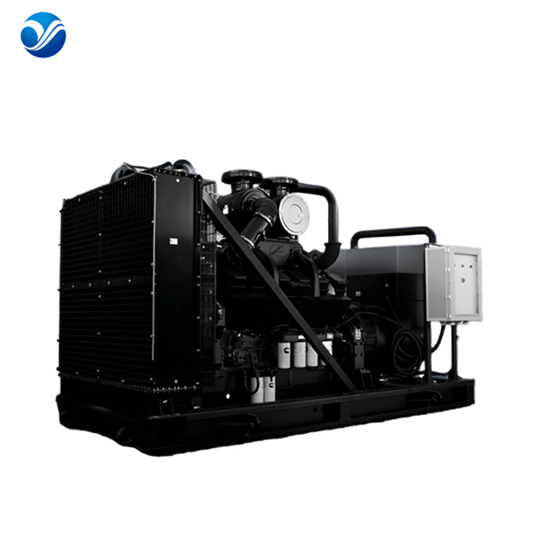
Enclosure design drastically alters thermal dynamics. An open generator manufacturer tests units with unrestricted ambient airflow. The testing environment allows heat to dissipate naturally. The focus remains purely on the engine and alternator thermal limits. The radiator fan draws air without static pressure resistance. This represents the best-case scenario for cooling efficiency. We often see open skids perform flawlessly on the test stand because they aren't fighting for air.
Conversely, a silent generator manufacturer faces complex aerodynamic challenges. Acoustic enclosures restrict airflow to trap sound waves. Intake baffles and exhaust attenuators create significant static pressure. The radiator fan must work harder to pull air through these restrictions. Load testing inside the canopy is mandatory. It verifies that the cooling system prevents overheating under 100% load despite the restricted airflow. If the enclosure design is flawed, the engine will derate or shut down due to high coolant temperatures. We use anemometers to measure airflow velocity across the radiator core during these enclosed tests.
Modular power plants require specialized testing protocols. A container generator manufacturer must evaluate ISO container ventilation. These units often feature motorized louvers and secondary cooling fans. Testing focuses on high-ambient temperature derating. The manufacturer must prove the container can reject heat effectively when placed in harsh environments. They monitor internal ambient temperatures closely during the full-load run to ensure the alternator does not ingest pre-heated air. We place thermal probes at the alternator air intake to ensure it stays within the 40°C design limit.
Mobile power adds mechanical stress to the equation. A trailer generator manufacturer performs rigorous vibration and structural integrity checks during full-load testing. A diesel engine operating at 100% load generates massive torque. This torque transfers directly to the chassis. Technicians verify chassis stability under maximum load. They check for harmonic resonance that could fracture fuel lines or loosen electrical connections. The trailer must absorb this energy without compromising the equipment. We inspect all weld seams on the trailer frame after a 4-hour full-load run.
The National Fire Protection Association (NFPA) sets strict standards for Emergency and Standby Power Systems (EPSS). NFPA 110 dictates specific performance criteria. Type 10 requirements are the most rigorous. The system must start, reach rated speed, and assume the full required load within exactly 10 seconds. This rapid response is non-negotiable for life-safety applications. Factory load testing proves the engine block heater, starter motor, and fuel system can meet this 10-second mandate reliably. We time this with digital oscilloscopes to prove compliance down to the millisecond.
Regional Authorities Having Jurisdiction (AHJs) enforce these standards. However, AHJ enforcement varies by location. Different municipalities adopt different editions of NFPA 110, such as the 2010, 2013, 2016, or 2019 versions. Manufacturers must align their FAT data structure to satisfy these localized legal requirements. Providing generic test data often results in failed site inspections. The documentation must explicitly address the metrics demanded by the local AHJ. We maintain a database of regional AHJ requirements to ensure our FAT reports pass inspection on the first try.
Extended operation at light loads damages diesel engines. This practice causes wet stacking. Wet stacking is the accumulation of unburned fuel and carbon in the exhaust system. When combustion temperatures remain low, fuel does not burn completely. It coats the exhaust valves, turbocharger, and silencer with a thick, oily residue. This degrades performance and creates a severe fire hazard. We see this constantly on sites that only run weekly no-load tests.
Manufacturers use full-load testing to prevent and reverse this condition. The engine must reach critical exhaust gas temperature thresholds. These thresholds typically require running at least 30% to 40% of rated capacity. Reaching high exhaust temperatures properly seats the piston rings. It also burns off uncombusted fuel deposits. Documenting these temperatures during the FAT proves the engine achieved optimal combustion efficiency. We install pyrometers directly in the exhaust manifold to log these temperatures during the test.
Site commissioning requires extensive paperwork. The AHJ demands specific load test reporting for compliance. This documentation is required for safety certifications and occupancy permits. The report must include continuous run logs, transient response graphs, and thermal stabilization charts. Without this verified data, inspectors will reject the installation, delaying facility operations. You must hand the inspector a bound report showing the exact serial number of the unit tested.
| Required FAT Document | Purpose for AHJ Inspection | Data Points Included |
|---|---|---|
| Transient Response Graph | Proves ISO 8528-5 compliance | Voltage dip %, Frequency droop %, Recovery time (ms) |
| Thermal Run Log | Verifies cooling system adequacy | Coolant temp, Oil pressure, Ambient temp over 4 hours |
| NFPA 110 Type 10 Certificate | Validates life-safety readiness | Cranking time, Time to rated speed, Time to load acceptance |
| Exhaust Pyrometer Log | Proves prevention of wet stacking | Exhaust gas temperature at 25%, 50%, 75%, and 100% load |
Deploying untested equipment introduces severe operational risks. The primary danger is voltage collapse. Unverified alternators often fail to provide necessary short-circuit fault clearing current. If a downstream breaker faults, the alternator must supply massive current instantly to trip the breaker and isolate the fault. If the alternator collapses under this demand, the entire facility loses power. Voltage stability is the foundation of electrical safety. We have seen cheap alternators literally melt their windings during a fault because they were never tested at full capacity.
Mechanical flaws lead directly to frequency instability. Lagging engine governors cannot maintain a steady 60Hz or 50Hz output. This instability wreaks havoc on frequency-sensitive facility equipment. Variable Frequency Drives (VFDs) will fault and shut down HVAC systems. Automated manufacturing robotics will lose synchronization. The resulting downtime costs far exceed the price of proper factory testing. You cannot run a modern data center on dirty, unstable power.
Buyers must protect their investments through strict procurement standards. You need a framework for evaluating a manufacturer's FAT documentation. Do not accept summary sheets. Demand raw data. Specify exactly what data points must be present in the final report. Require recovery time in milliseconds. Demand maximum voltage dip percentages. Insist on continuous run thermal logs. If a supplier hesitates to provide this data, find another vendor. We always invite clients to witness the FAT in person to build trust.
Verifying load acceptance is the most critical quality control measure in generator manufacturing. Without documented load bank and block load testing, a generator's nameplate rating is purely theoretical. You cannot trust unverified power equipment to protect critical infrastructure. Procurement teams should immediately disqualify manufacturers who cannot provide comprehensive, unit-specific FAT reports detailing ISO 8528-5 transient response, exhaust temperature data, and NFPA 110 compliance.
Write specific load step requirements and maximum allowable voltage dips directly into your initial RFPs.
Demand witnessed factory testing via live video feed or in-person visits for all mission-critical deployments.
Require that all FAT reports include both resistive and reactive load testing data to prove true kVA capacity.
Verify the testing occurs in the final enclosure configuration to ensure accurate thermal data.
A: Block load testing applies 100% of the generator's rated load in a single step. This verifies the engine and alternator can handle sudden, massive electrical demand without stalling or exceeding acceptable voltage and frequency drop limits.
A: Generators fail due to improperly tuned governors, undersized alternators, or turbocharger lag. Other culprits include restricted fuel delivery systems, clogged air intakes, or inadequate cooling loop designs that cause rapid overheating.
A: Resistive tests simulate pure active power (kW) like heating and lighting. Reactive tests add inductive loads (kVAR) to simulate the starting currents of large motors and transformers. Combining them tests the alternator's true kVA capacity.
A: NFPA 110 requires emergency standby systems to assume the required load within a specified timeframe, such as 10 seconds for Level 1 Class 10 systems. It mandates documented load testing at specific exhaust temperatures to guarantee readiness.
A: Yes, provided the manufacturer properly engineered the cooling and ventilation systems. The design must handle the massive heat rejection of a 100% block load within the confined, airflow-restricted space of the acoustic enclosure.
A: Wet stacking is the buildup of unburned fuel and carbon in the exhaust system due to running at light loads. Load bank testing forces the engine to reach optimal high operating temperatures, burning off these dangerous deposits.


